"How to program little things"
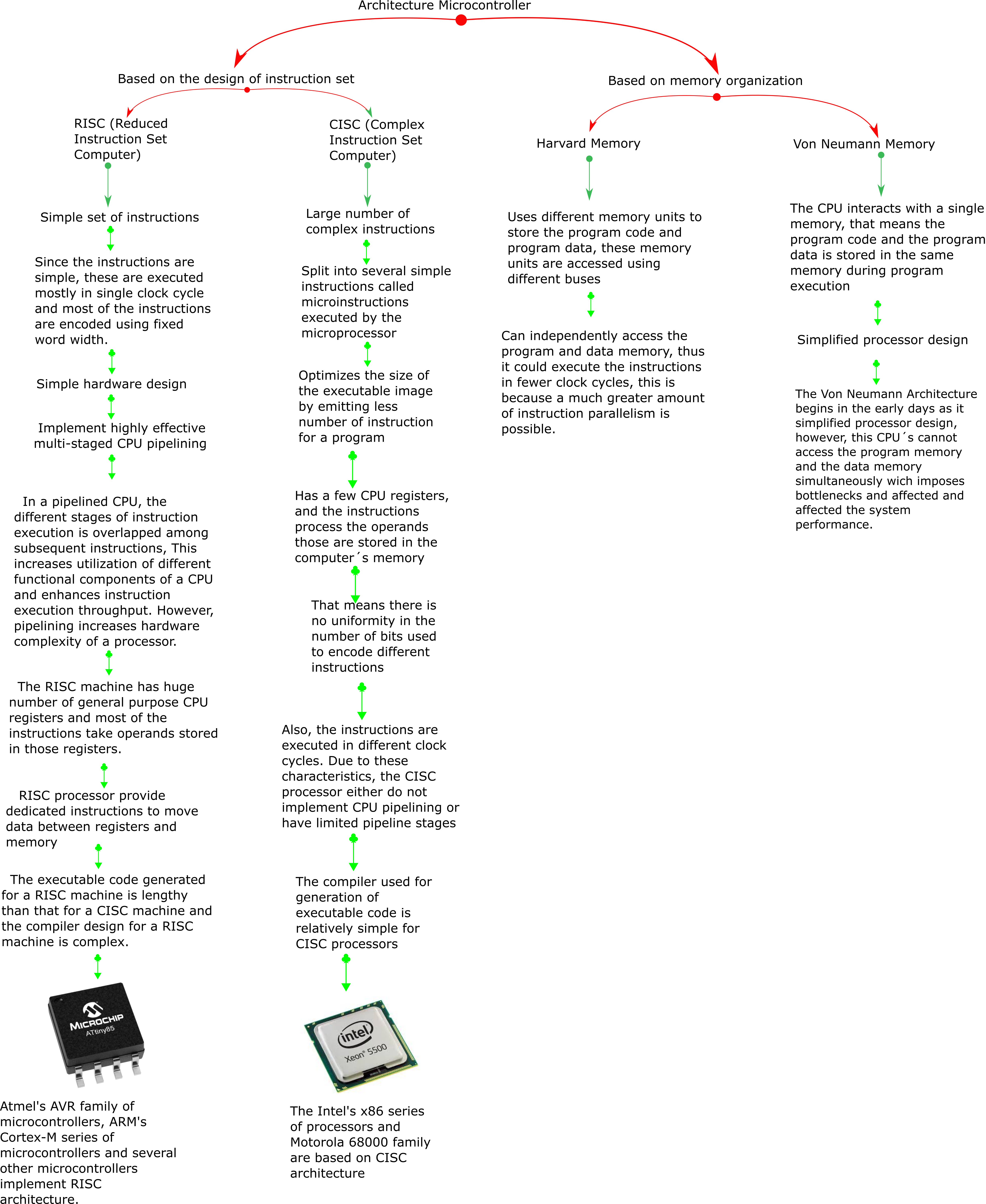
It is necessary to differentiate between two different architectures, one based on the design of the instruction set, and the other in the memory organization:
*The following scheme is based on this VIDEO
Atmel 8-bit AVR Microcontroller with 2/4/8K Bytes In-System Programmable Flash
ATtiny25/V / ATtiny45/V / ATtiny85/V
-->DatasheetATTINY45 is high performance, low power controller from ATMEL. It is an 8 bit controller based on Advanced RISC architecture. It is one of members of ATTINYXX series, popular because of its small size and features.
Sub sistems diagram / block diagram
 - Adobe Acrobat Reader DC.png)
Memory
- Registers: For operating
- Static Ram: Store data for quickly access
- EEPROM: Memory that keep the value when the power is turn off.
- Flash: Where you store programs
The AVR core combines a rich instruction set with 32 general purpose working registers. All 32 registers are directly connected to the Arithmetic Logic Unit (ALU), allowing two independent registers to be accessed in one single instruction executed in one clock cycle. The resulting architecture is more code efficient while achieving throughputs up to ten times faster than conventional CISC microcontrollers.
The lower 224/352/607 Data memory locations address both the Register File, the I/O memory and the internal data SRAM. The first 32 locations address the Register File, the next 64 locations the standard I/O memory, and the last 128/256/512 locations address the internal data SRAM.
The ATtiny25/45/85 contains 128/256/512 bytes of data EEPROM memory. It is organized as a separate data space, in which single bytes can be read and written. The EEPROM has an endurance of at least 100,000 write/erase cycles.
The ATtiny25/45/85 contains 2/4/8K bytes On-chip In-System Reprogrammable Flash memory for program storage. Since all AVR instructions are 16 or 32 bits wide, the Flash is organized as 1024/2048/4096 x 16. The Flash memory has an endurance of at least 10,000 write/erase cycles. The ATtiny25/45/85 Program Counter (PC) is 10/11/12 bits wide, thus addressing the 1024/2048/4096 Program memory locations. “Memory Programming” on page 146 contains a detailed description on Flash data serial downloading using the SPI pins.
Peripherals
- Ports/pins:
 - Adobe Acrobat Reader DC.png)
- Analog/digital to converter: Measure the voltaje and turn it into an number
The ATtiny25/45/85 features a 10-bit successive approximation Analog to Digital Converter (ADC). The ADC is connected to a 4-channel Analog Multiplexer which allows one differential voltage input and four single-ended voltage inputs constructed from the pins of Port B. The differential input (PB3, PB4 or PB2, PB5) is equipped with a programmable gain stage, providing amplification step of 26 dB (20x) on the differential input voltage before the A/D conversion. The single-ended voltage inputs refer to 0V (GND).
- Comparator: compare two voltajes, only tell if is greater or less than, is faster than the A/D
When entering Idle mode, the Analog Comparator should be disabled if not used. When entering ADC Noise Reduction mode, the Analog Comparator should be disabled. In the other sleep modes, the Analog Comparator is automatically disabled. However, if the Analog Comparator is set up to use the Internal Voltage Reference as input, the Analog Comparator should be disabled in all sleep modes. Otherwise, the Internal Voltage Reference will be enabled, independent of sleep mode. Refer to “Analog Comparator” on page 118 for details on how to configure the Analog Comparator.
- Timer: Meassure time/Counter: Meassure counts
8-bit Timer/Counter with Prescaler and Two PWM Channels
- pwm (pulse width modulation): Turnning an pin on and off very very quickly, much more power in a much smaller circuit with less heat.
High Frequency PWM Outputs with Separate Output Compare Registers
Programming the microcontroller
Program the board using c/c++
For programming the board, I use Atmel Studio 7. Is the integrated development platform (IDP) for developing and debugging all AVR® and SAM microcontroller applications. The Atmel Studio 7 IDP gives a seamless and easy-to-use environment to write, build and debug applications written in C/C++ or assembly code. It also connects seamlessly to the debuggers, programmers and development kits that support AVR® and SAM devices.
Install Atmel Studio 7 in Windows 10 could be tricky. Further, I use the USBasp as a programmer, but, since this programmer is not of the Atmel brand, it is necessary to configure the program so that it can be used as an external programmer/tool. In the following tutorial the whole process is very well explained, from the software installation, then the creation of an external tool and how to use the system to program a microchip:
- Setting up Atmel Studio for USBasp and AVR Programming
- Zadig: is a Windows application that installs generic USB drivers, such as WinUSB, libusb-win32/libusb0.sys or libusbK, to help you access USB devices. This in case the system does not recognize the USBasp, at the moment to try to load the code in the microchip. It was useful for me.
Once the program configuration is achieved, that is, to successfully load a program into the microchip, it is possible to load any code in the c / c ++ language.
I program this board, designed by Neil:
*Since it is an update, I used one of the boards I made for Networking and Communications week, the manufacturing process is better detailed there, but the main thing in this case is that a Attiny 45 microchip was used.
As mentioned above, when using a programmer that is not explicitly included in the program, an external tool must be configured, in this case it is important to follow the instructions to the letter, place the necessary paths and arguments. In the case of the arguments used, it must be commented that the type of microchip to be programmed must be detailed, in this case it is an Attiny 45, and its abbreviated form must be written which is t45 ...
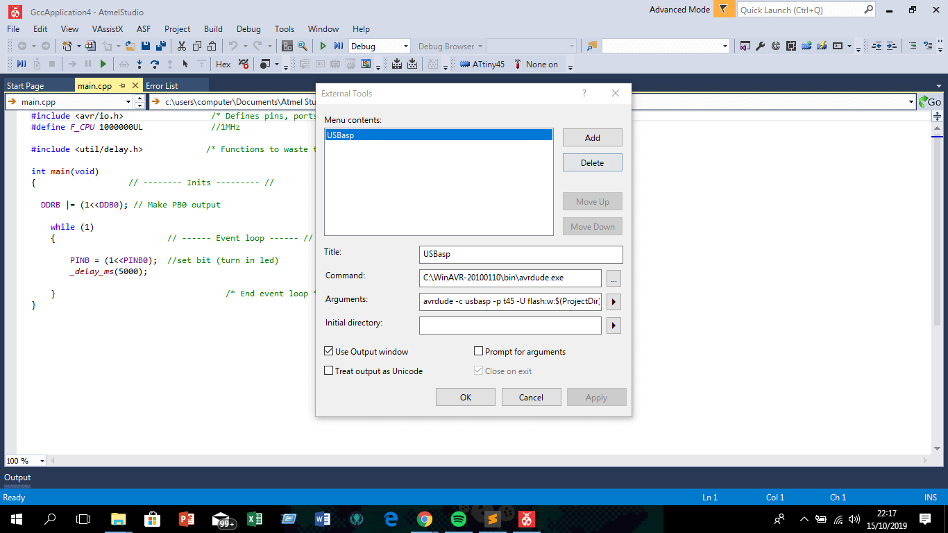
The argument for use the USBasp was:
avrdude -c usbasp -p t45 -U flash:w:$(ProjectDir)Debug\$(TargetName).hex:i
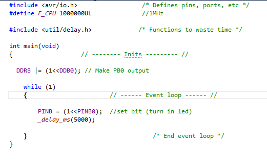
Once the Atmel Studio is set up, is able to read the code, I use a simple blink c code.
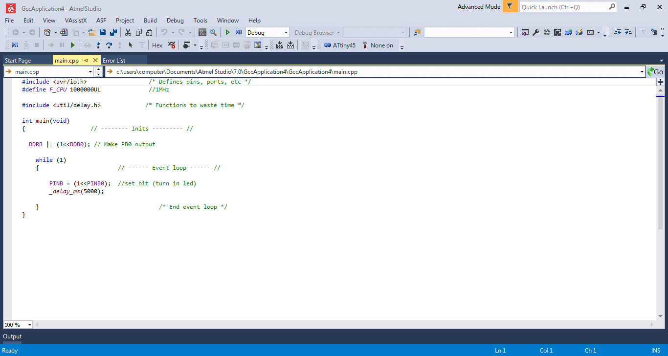
Zoom over the code...
The video show the process for load a c code in the board usign Atmel Studio
Program the board using Arduino c++
The Arduino integrated development environment (IDE) is a cross-platform application (for Windows, macOS, Linux) that is written in the programming language Java. It is used to write and upload programs to Arduino compatible boards, but also, with the help of 3rd party cores, other vendor development boards.
The source code for the IDE is released under the GNU General Public License, version 2.The Arduino IDE supports the languages C and C++ using special rules of code structuring. The Arduino IDE supplies a software library from the Wiring project, which provides many common input and output procedures. User-written code only requires two basic functions, for starting the sketch and the main program loop, that are compiled and linked with a program stub main() into an executable cyclic executive program with the GNU toolchain, also included with the IDE distribution. The Arduino IDE employs the program avrdude to convert the executable code into a text file in hexadecimal encoding that is loaded into the Arduino board by a loader program in the board's firmware.
There are currently a lot of information about manage the Arduino IDE, but for use the Attiny microchip family is necesary to install a librarie for a well performance, this process was covered in the Electronics Design week.
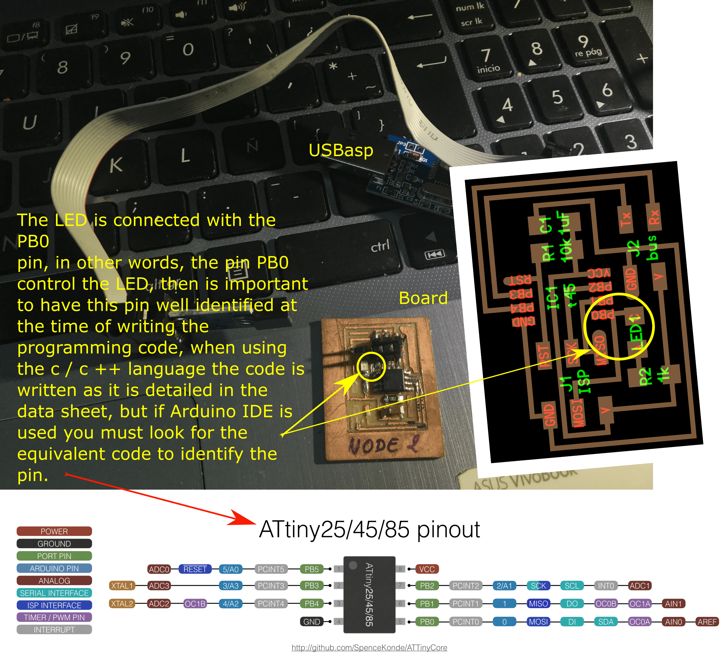
The above picture shows equivalent pins of the Attiny 45 for the Arduino IDE and is the same idea than in Atmel Studio, for code is necessary to know how to name the pin that is going to control the led, in this case.
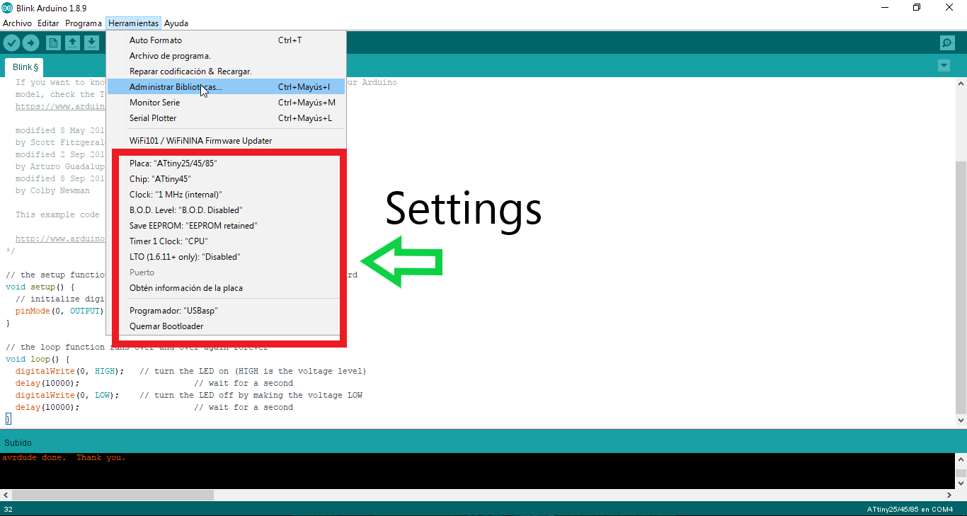
Arduino IDE settings for programing an Attiny 45
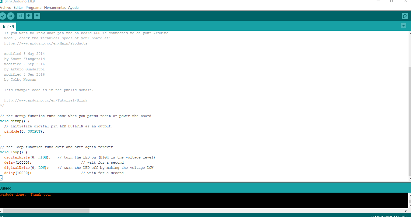
...and the code itself

Asignment goals
- Compare the performance and development workflows for other architectures (Group assignment).
- Read a microcontroller data sheet.
- Program your board to do something, with as many different programming languages and programming environments as possible.
Atmel Studio Files
Arduino Files
Learning outcomes
- Identify relevant information in a microcontroller data sheet.
- Implement programming protocols.
Have you?
- Documented what you learned from reading a microcontroller datasheet.
- What questions do you have? What would you like to learn more about?
- Programmed your board.
- Described the programming process/es you used.
- Included your code.